Existing Systems Update Training
Technical Feasibility
The following changes have been implemented into the specification for code compliance for the following product types: PV, PV + Storage, BIPV, and BIPV + Storage. You can review the Release notes here.
Eligibility
- The existing SolarApp+ eligibility criteria will be altered as such:.
“No existing PV or ESS” - Delete- “May include an existing PV system with (1) module type and multiple PV inverters” - Add
“All power production inverter outputs have the same point of connection” - Delete“May include up to (2) points of interconnection to premises wiring systems” - Add
Power Production Source Point of Interconnection
- Each inverter and ESS shall identify the first point of interconnection, naming either the busbar or conductor where source output and house loads interact.
- The existing SolarApp+ eligibility criteria will be altered as such:.
- Contractors may detail the following interconnection locations for inverters and ESS:
- Backup Lugs
- Main Service Panel
- Existing Subpanel (not shown)
- New Subpanel
- New Non-backup panel (not shown)
- Service Feeders
- Subpanel Feeders
- Non-backup lugs
- PV Combiner panels without loads are not considered the first point of interconnection, rather, the location of the Overcurrent Protective Device (OCPD) protecting the combiner panel, provided it is installed in a panel with house loads, should be identified as the first point of interconnection.
- Inverters and Energy Storage Systems (ESS) do not need to have the same point of interconnection if the manufacturers instructions, and the product listings, allow this configuration.
SolarAPP+ can detail up to (2) unique points of interconnection.
Existing system detail
- An installer may detail the addition of a new solar or solar and storage system in parallel with an existing solar system. The software is not intended to allow for the modification or alteration of an operational solar system.
- SolarAPP+ does not consider the relocation of the existing solar system overcurrent protective device as an alteration to the existing system. Oftentimes, relocation of the system OCPD is warranted and presents the best options for installation, but this is not required.
- Existing system equipment must be available for selection on the California Energy Commission's list of approved equipment to ensure that equipment maintains an appropriate safety listing.
- Archived list equipment may not be available. In these cases, the system should be permitted using the traditional method to ensure that existing equipment is safe for continued use.
- Installers detail a single module manufacturer, model number, and quantity.
- Installers may detail multiple inverter models, including the inverter manufacturers, model numbers, and quantities.
- Installers detail the point of interconnection for the existing system with the following options:
- Main Service Panel
- Existing Subpanel
- New Subpanel
- New Non-backup panel
- Service Feeders
- Subpanel Feeders
- Backup Lugs
Non-backup lugs
Busbar configurations
- Based on the question logic, installers will no longer need to name a busbar “combiner panel.” The Installer will indicate that a new subpanel will be used for combining generation sources. No house loads may be relocated to a dedicated power production source combiner panel.
- The installer will identify the point of interconnection for the combiner panel as the location where the combiner panel OCPD is located on the same bus or conductor with house loads using the following options:
- Main Service Panel
- Existing Subpanel
- New Subpanel
- New Non-backup panel
- Service Feeders
- Subpanel Feeders
- Backup Lugs
- Non-backup lugs
- The installer will identify each power production source that is connected to the combiner panel busbar. SolarAPP+ will individually ask for the point of interconnection of new inverters, batteries, and the existing system.

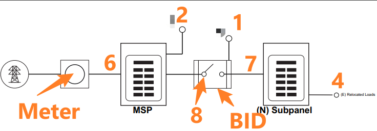
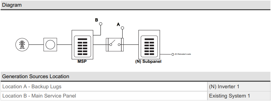
Diagrams
- SolarAPP+ will indicate the points of interconnection, along with their paired source(s), as location A or B.
- Location A and B can be any of the following locations, see diagram:
- Backup Lugs
- Main Service Panel
- Existing Subpanel (Not shown)
- New Subpanel
- New Non-backup panel (Not shown)
- Service Feeders
- Subpanel Feeders
- Non-backup lugs
- New and Existing power production systems may be combined at the same point of interconnection, but do not have to be.
- NOTE: PV Source combiner panels without loads are not shown on the diagram but are indicated in the checklist. The point of interconnection is the location where a source OCPD is on the same bus or conductor serving house loads.
Example Project Parameters for calculations
| Equipment | MFG and Model | Interconnection Location |
| New PV Inverter | Solaredge SE6000H | Backup Lugs (BID) |
| New PV Module | JA Solar JAM54S31-395/MR | Qty 8 |
| New ESS | Solaredge BAT-10k1P | Backup Lugs (BID) |
| Existing PV inverter | Solaredge SE3800A | Main Service panel |
| Existing PV module | QCells Q.PEAK Duo-G8+ 350 | Qty 15 |
| (N) Backup Load center | Max Continuous calculated load = 30A |
Calculations
- Existing PV array area is calculated based on CEC data pulled by the module model number to inform rooftop access pathways and setbacks.

- The tool will calculate existing system output using CEC data and contractor inputs.
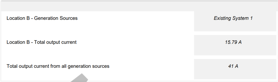
- Based on the identified point of interconnection, SolarAPP+ will sum the maximum AC output currents for each power production source, ensuring compliance with the electrical code by calculating the backfeed contribution at every busbar and conductor within the system.

- In the example above, none of the generation sources land in the new backup load center, therefore it is not subject to backfeed. Generation sources and grid power both combine at the new backup load centers overcurrent protective device.
- When isolated from the grid and the existing PV system, the new PV and ESS, interconnected at point A, the backup lugs of the backup initiation device, provide 25.21A of backfeed to the feeders supplying the New Backup Load Center.
- When the energy storage system (ESS) is operating normally, the maximum continuous duty current of 31.51A is present at the feeders supplying the New Backup Load Center .